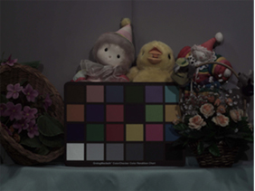
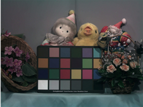
Panasonic Japan announced today that they have developed the technology for producing highly sensitive image sensors by using unique “micro color splitters“. Read the attached press release for more details:
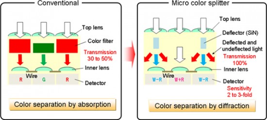
Left image: conventional method using a color filer, right image: Developed method using a micro color splitter.
Osaka, Japan – Panasonic Corporation has developed unique “micro color splitters”, which separate the light that falls on image sensors by exploiting light’s wavelike properties. Applying them to actual image sensors allows bright color images to be achieved even under low-light conditions. This development makes color filters unnecessary by using the micro color splitters that control the diffraction1 of light at a microscopic level. Panasonic has achieved approximately double the color sensitivity in comparison with conventional sensors that use color filters.
Image sensors are used in devices like smartphones, digital still cameras and video cameras, as well in security, vehicle parking, office, and healthcare applications – anywhere, in fact, that digital imaging is needed. Conventional color image sensors use a Bayer array2, in which a red, green, or blue light-transmitting filter is placed above each sensor. These filters block 50 – 70% of the incoming light before it even reaches the sensor. Progress is being made in increasing the resolution of image sensors used in mobile and other devices by reducing pixel size, but demand for higher-sensitivity cameras is also increasing. Panasonic has developed a new technology that can be applied to existing or future sensors to enable them to capture uniquely vivid color images.
The developed technology has the following features.
- Using color alignment, which can use light more efficiently, instead of color filters, vivid color photographs can be taken at half the light levels needed by conventional sensors.
- Micro color splitters can simply replace the color filters in conventional image sensors, and are not dependent on the type of image sensor (CCD3or CMOS4) underneath.
- Micro color splitters can be fabricated using inorganic materials and existing semiconductor fabrication processes.
This development is based on the following new technology.
- A unique method of analysis and design based on wave optics that permits fast and precise computation of wave-optics phenomena.
- Device optimization technologies for creating micro color splitters that control the phase of the light passing through a transparent and highly-refractive plate-like structure to separate colors at a microscopic scale using diffraction.
- Layout technologies and unique algorithms that allow highly sensitive and precise color reproduction by combining the light that falls on detectors separated by the micro color splitters and processing the detected signals.
Panasonic holds 21 Japanese patents and 16 overseas patents, including pending applications, for this development.
This development is described in general terms in the Advance Online Publication version of Nature Photonics issued on February 3, 2013.
More on the Technology
1. Unique method of analysis and design based on wave optics permitting fast and precise computation of wave-optics phenomena
FDTD5 is widely used to analyze light in wave form, but its heavy computation workload has up to now made it impractical for designing micro color splitters. On the other hand, BPM6 is an effective method of fast computation, but it has lower precision than FDTD and cannot accurately simulate color splitting. This prompted Panasonic to develop a practical and original design method that permits fast and precise computation of wave-optics phenomena. This technology allows the precise modeling of optical phenomena such as reflection, refraction, and diffraction by modeling spaces in regions with different optical constants and applying BPM to the spaces. This method can be applied not only to the design of micro color splitters, but can be extended to the design of other nano-scale optical processing systems.
2. Device optimization technologies leading to the creation of micro color splitters that control the phase of the light passing through a transparent and highly-refractive plate-like structure and use diffraction to separate colors on a microscopic scale
Color separation of light in micro color splitters is caused by a difference in refractive index between a) the plate-like high refractive material that is thinner than the wavelength of the light and b) the surrounding material. Controlling the phase of traveling light by optimizing the shape parameters causes diffraction phenomena that are seen only on a microscopic scale and which cause color separation. Micro color splitters are fabricated using a conventional semiconductor manufacturing process. Fine-tuning their shapes causes the efficient separation of certain colors and their complementary colors, or the splitting of white light into blue, green, and red like a prism, with almost no loss of light.
3. Layout technologies and unique algorithms that enable highly sensitive and precise color reproduction by overlapping diffracted light on detectors separated by micro color splitters and processing the detected signals
Since light separated by micro color splitters falls on the detectors in an overlapping manner, a new pixel layout and design algorithm are needed. The layout scheme is combined and optimized using an arithmetic processing technique designed specifically for mixed color signals. The result is highly sensitive and precise color reproduction. For example, if the structure separates light into a certain color and its complementary color, color pixels of white + red, white – red, white + blue, and white – blue are obtained and, using the arithmetic processing technique, are translated into normal color images without any loss of resolution.
Notes:
- 1. Diffraction
- Behavior of light as a wave on the wavelength (nanometer) scale. Various phenomena occur when a wave encounters an obstacle.
- 2. Bayer array
- The arrangement of color filters used in most single-chip digital imaging sensors used in digital cameras, camcorders, and scanners to create a color image. The filter pattern is 50% green, 25% red and 25% blue.
- 3. Charge Coupled Device Image Sensor (CCD sensor)
- A type of solid-state image sensing device for digital imaging, used in digital video cameras of all types. It has higher sensitivity and lower noise than other sensing devices.
- 4. Complementary Metal Oxide Semiconductor Image Sensor (CMOS sensor)
- A solid-state image sensing device for digital imaging using CMOS.
- 5. Finite-Difference Time-Domain method (FDTD)
- FDTD is a versatile modeling technique used to solve Maxwell’s equations by spatial and temporal discretization.
- 6. Beam Propagation Method (BPM)
- A numerical analysis technique in electromagnetics for solving the Helmholtz equation under conditions of a time-harmonic wave.


